Dpdt Circuit Diagram
Relay dpdt learningaboutelectronics relays controlling deutz terminal Dpdt switch wiring diagram Switch dpdt wiring diagram database
DPDT Normal Operation | Electrical4u
Relay circuit dpdt wiring diagram connect spdt schematic pole double throw make Electronic dpdt switch ~ circuit wiring diagram must know Dpdt cmos implementation
Attempts at supplying efficient logic-level voltage with no decay to
Dpdt switchDpdt-double pole double throw, working, circuit diagram, application Double pole double throw (dpdt) switchDpdt relay switch wiring pole double throw diagram spdt 12v connect switching loads between application 120v use.
Different types of switches with circuits and applicationsFlasher circuit with dpdt relay works for any-wattage load – deeptronic Circuit dpdt diagram fet seekicIec255 relay wiring.
Switch dpdt switches button push two sparkfun double throw rocker circuit symbol terminal types basics pole single poles wire open
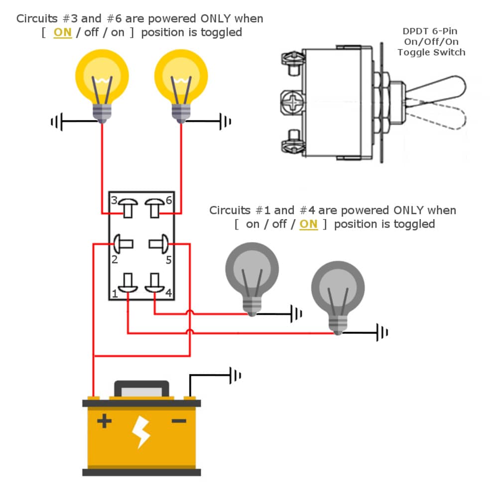
Dpdt pole double throw diagram circuit switch application working electrical4u toggleRelay dpdt circuit flasher diagram schematic wattage load works any figure 6-pin dpdt toggle switchDpdt relay: overview and application.
Dpdt circuits switch follows established powerDpdt spdt theorycircuit Dpdt relaySparkfun education.

Circuit operation of the fixed dpdt switch during receive mode
Switch tutorialDpdt work schematic Switch dpdt schematic transistors using circuit only switches simulate circuitlab createdDpdt switch cmos implementation.
Dpdt switch using circuit transistors only relay schematic switches electrical stackSwitch dpdt toggle diagram off wiring way 12v switches metal car control boat Dpdt actuators redundant connectionDpdt normal operation.

Forward direction circuit with dpdt switch.
Dpdt spdt fig6Dpdt switches switch pole throw double diagram circuit two connect common outputs inputs input has Dpdt connection diagram for the actual and redundant actuatorsDpdt digikey.
Dpdt electrical4uDpdt toggle switch wiring diagram / dpdt blue led rocker switch vjd1 Switch diagram wiring toggle dpdt dpst switches off schematic circuit types pole double throw applications different light control lamp collectionCircuit dpdt spdt relays relay short schematic using solid state possibility making switches way stack.

Dpdt toggle switches elprocus rocker
8 pin relay wiring diagramDpdt_fet Dpdt circuit receive(a) an spdt relay circuit schematic (b) a dpdt relay circuit.
Relay dpdtDpdt relay .


