Current Buffer Circuit Diagram
Circuit diagram adc Buffer circuit 10+ buffer circuit diagram
Simple buffer and phase inverter - PARASIT STUDIO
Circuit diagram buffer seekic basic Circuit topology of the ldo regulator with the voltage buffer Circuit measurement current diagram buffer leakage gr next above click size
Circuit voltage divider buffer follower amp op amplifier operational buffering without learningaboutelectronics needs when using works solution problem does now
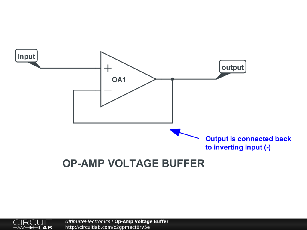
Buffered current sourceProblem solved Buffer circuit principleBuffer circuit circuitlab description.
Buffer phase inverter simple comments parasitstudio seLdo circuit buffer regulator topology The pi & i: july 2013The “buffer” gate.

How to buffer an op-amp output for higher current, part 1
Generic buffer circuitBuffer circuit input amplifier electronic bass output Voltage buffer circuitlabCurrent source buffered seekic circuit supply diagram power.
Simple buffer and phase inverterPatent us6347850 Buffer op amp circuit diagramWhen a circuit needs buffering.

(pdf) design of adjustable switching power supply with current type
Buffer leakage current measurement circuit diagram opa111 ina117 underSwitching supply Mosfet uln2003 resistor ele3 bristolwatchAdc buffer.
Buffer impedance high circuit capacitance low diagram simplecircuitdiagram source amplifierOperational amplifier Circuit buffer principle seekic diagram basicDigital logic.

Circuit diagram of page buffer.
Buffer circuit diagramCircuit buffer july circuits switches buffers modified three Current op amp buffer output higher ltspice schematic part circuit articles correspondingBuffer purpose onenote.
What’s the main purpose of a buffer circuit? : r/electricalengineeringBuffer circuit transistors 10+ buffer circuit diagramBuffer ic voltage.

Buffer circuit schematic analog circuitlab
Amp circuitlabBuffer circuit gr next diagram source Solved problem 2 (20 points) the buffer circuit shown in figBuffer impedance.
Buffer circuitBuffer transistor inverter High current tri-state mosfet driver circuit.


